| |
| | |
notes on making
A COLLAR RIG
for kite aerial photography
|
|
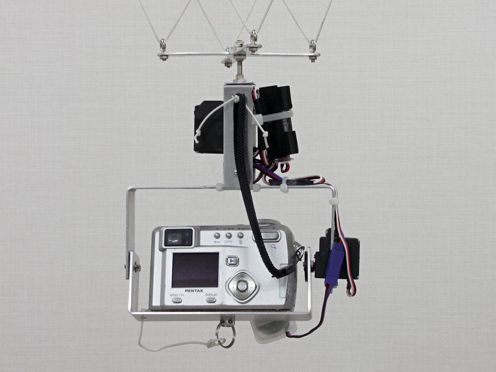
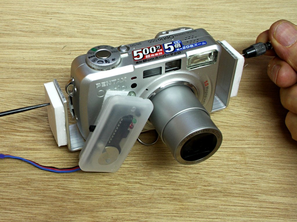
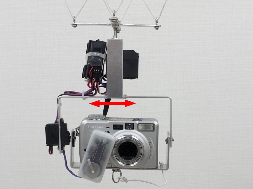
 Front view with a Tucit Quadro
 Rear view with a Tucit Duo
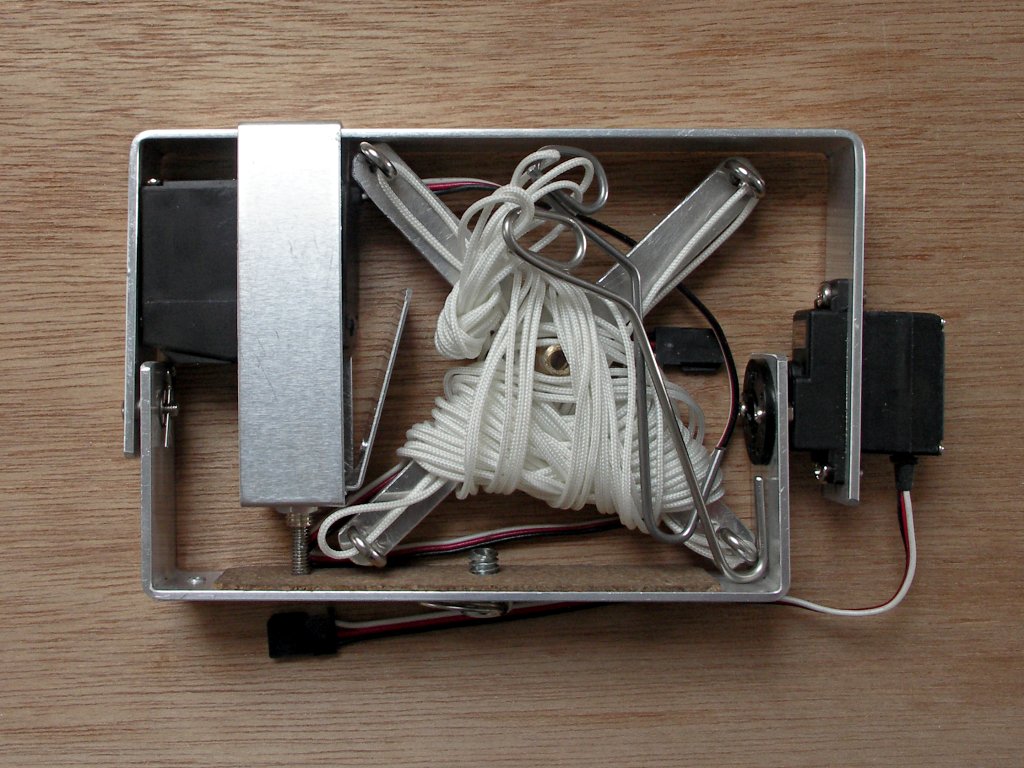 Folded for travel 10 x 16 x 2.5 cm
|
Collar rigs ideal for Tucit-X are but they are equally suitable for model aeroplane radio control systems.
When thinking about what makes a good object to fly in public places there can be only one priority. It isn't to do with photographs, it's safety. Always keep asking what if this thing lands on somebody's head.
Many things follow from this and the first is that the less parts you have the less can go wrong, the less weight and the less there is to fall off. So pointed things like legs which stick out have no place.
Another thing which follows is to make it as soft as possible. If your rig bumps on the ground then the chances are a corner will impact first. If the metal here is soft the corner will open up absorbing the energy. The more it deforms the more energy it absorbs and the better your camera will be protected. Afterwards you can use your fingers to bend the aluminium straight again.
Other than lightness other features which this rig has are its size and portability, ability to adjust balance for extras like video and the ability to accommodate all your present and future cameras without having to do a major rebuild each time.
Here are some ideas about building collar rigs. Hopefully publishing these details will attract suggestions for improvements.
|
|
|
1
|
BEFORE STARTING ...
|
|
|
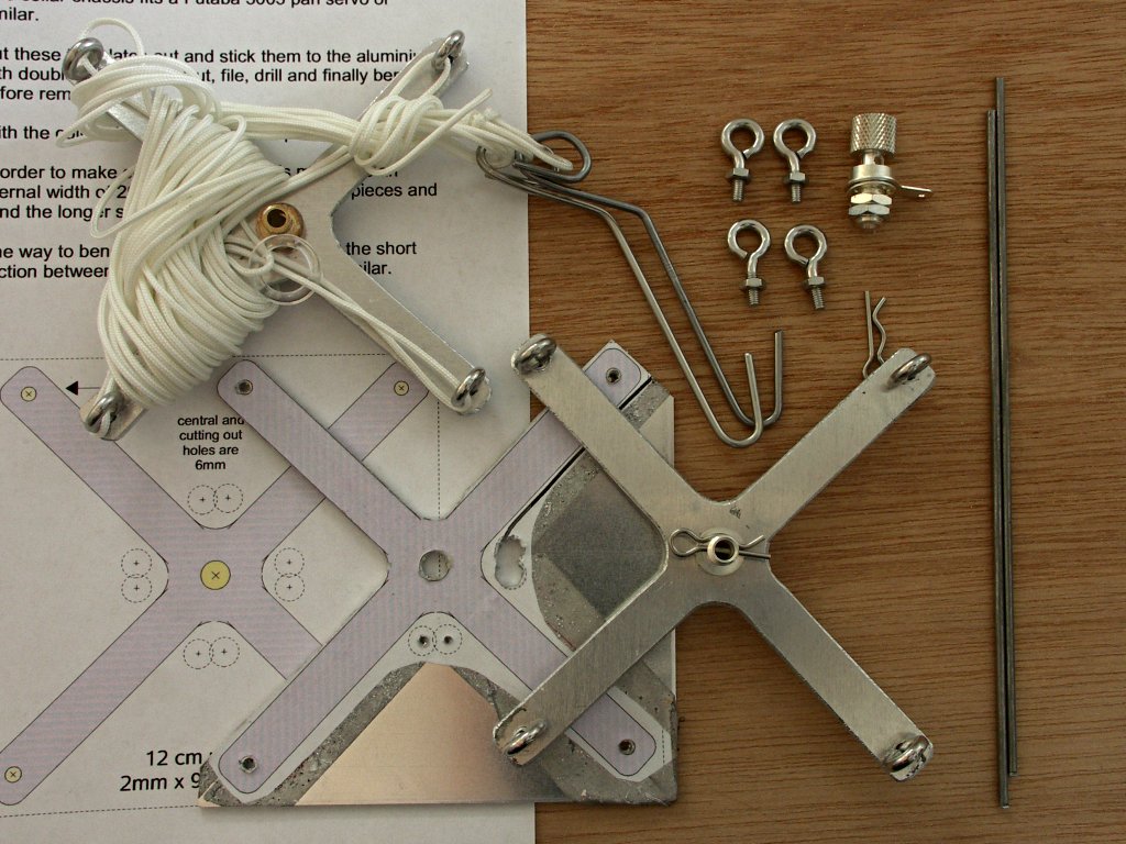
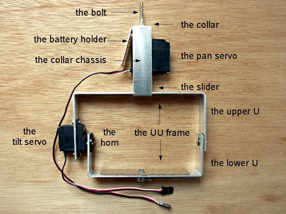 parts and names
|
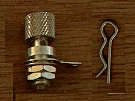
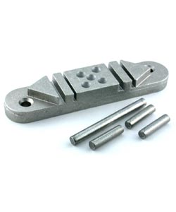
terminal and R pin
|
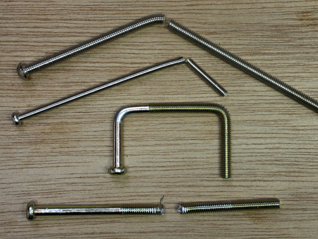
bolts
|

pin holes
|
|
1 All the pictures here are best seen at full size, so please click them. Please look first at the names of the main parts of this rig.
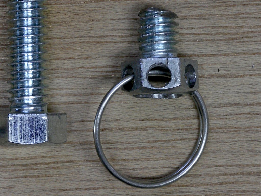
2 The collar is made from an electrical terminal, the sort which have 4 mm holes going all the way through them (some don't). There's usually a choice of colour but they must be 4 mm inside. You will need a second terminal for the picavet. If you can't get them they can be made by carefully sinking a 4 mm hole down a 6 mm bolt.
3 The central bolt which passes through last gear of the pan servo and then up through the collar is 6 cm long and 4 mm in diameter. It must be part threaded for much of its length and and better still completely unthreaded. Threads are weak points inviting fracture. Before using a bolt take another from the same batch, put it in a vice and attack it with a hammer. If it is brittle and won't bend at least 90º don't use it. When bolts are bent imperceptible fractures traverse them so never attempt to straighten them - always replace.
4 You will need to make tiny holes to put R pins through both 3 mm and 4 mm bolts. First invest some time in making a guide. An convenient thing to use is one of the nuts which comes with them. Make your mistakes on them and when successful get it insured. The picture above shows a 1.1 mm hole in a 3 mm bolt.
5 Building this rig requires a bench drill with an assortment of bits, a vice, a hacksaw and files, etc. You will need a nogis for measuring R pin and drill bit diameters. A metal bending tool for aluminium and a wire bending tool for the hangups are nice to have but are not at all essential.
6 Please download this pdf file of the aluminium templates. Pease note that sometimes the aluminium is 1 mm and sometimes 2 mm thick.
|
|
|
2
|
CONVERTING THE SERVO TO 360º
| |
|
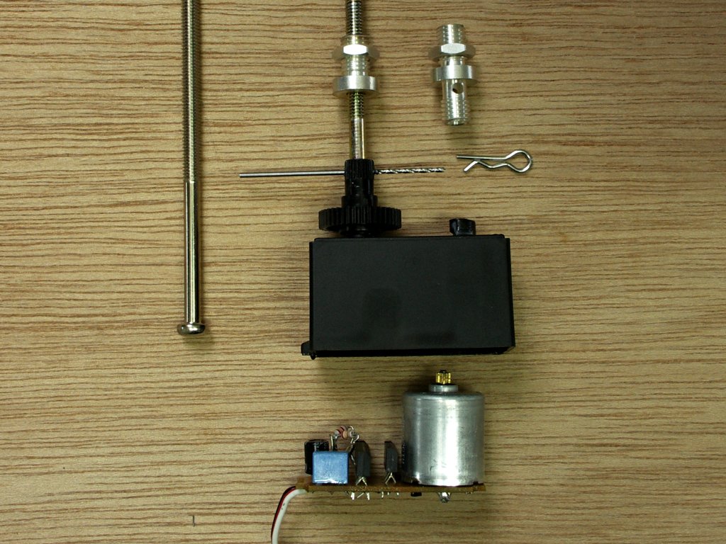
 Servo conversions
|
1 With Tucit you will have total control of your servo so there is no need for additional, external gears to slow it down.
2 There are a number of servos which you can use for panning, but they need to be big enough to take a 4 mm bolt. Here we use Futaba 3003 servos. These may not be cheap, but as you can buy spare gears your mistakes will be. (alternatives here)
3 Undo the screws underneath, pull of the top and note which way the gears go then prise out the pcb at the bottom.
|
4 The spindle of the potentiometer (picture left) is normally turned by the (large, black) final gear to provide feedback about where the servo has turned to. For continuous 360º rotation we need to fool the servo into thinking that it is always in its central position.
Option 1 (picture center)
Park the potentiometer in it's central position and snip the spindle off.
The fact that it's impossible to find the exact center position has made this way most unsatisfactory with radio control rigs because it results in the servo creeping when it's supposed to be off. But Tucit works on very different principles and so for Tucit this option is fine and your servo will not creep.
Option 2 (picture right)
Alternatively replace the potentiometer (normally 5K) with two 2.4K resistors as shown.
Before reassembling the servo cut or snip off the small lug on the top of the final gear so that it doesn't catch as it turns around.
|
|
3
|
FITTING THE PAN BOLT
|
|
|
 First method
 Second method
|
First method
1 Starting at the thin end of the final gear drill down using a smaller bit first and ending with a hole which is no larger than 3.5 mm.
2 Use a 6 mm bit preferably with a stopper and drill out the bottom of the final gear as shown in the diagram.
3 File the head of the bolt until it is just over 1 mm thick and slightly over 6 mm in diameter.
4 Put the two together. As you force the threaded end of the 4 mm bolt down the 3.5 mm hole in the gear you tap a thread into the plastic. As the gear passes onto the unthreaded metal keep turning in the same direction. If you use a Tucit this movement of the metal - screwing the bolt into the gear is the same direction as the default panning direction. There's no thread but the plastic grips better.
5 Now check your bolt is deep enough for the final gear to sit with its base in full contact with the casing underneath. If it doesn't you may have to file or drill a bit more.
|
6 What if your bolt is loose ? You have probably over-filed the sides of the head. Make another or make a washer. Make a small hole in a piece of a broad rubber band. Force it down the bolt to the head, trim it to size and push it in with the head.
7 After reassembling cut the bolt so that it extends 4 cms beyond the top of the gear and drill a hole for an R pin about 5 mm down from top.
8 Try never to twist your pan servo around by hand. On those occassions when you have to aim your camera in order to take 'static' shots remember the plastic thread. As seen from above only move your rig round clockwise, never anticlockwise.
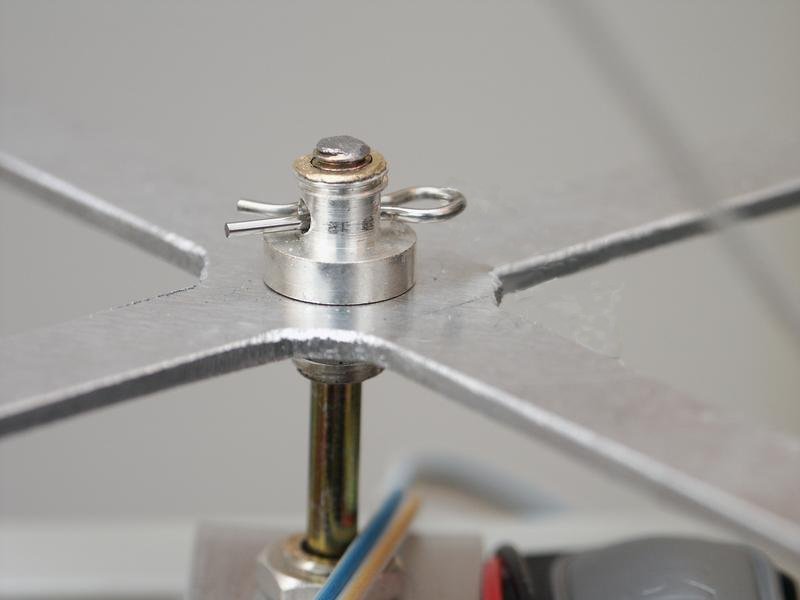
Second method
1 Drill out the final gear to 3.5 mm as above.
2 Take out the circuit board and motor and pass a bolt up through the hole as shown. You do not need to file the head at all.
3 Force the final gear down the bolt as above. Move it as far down as you can. Then when it's tight move it back 1 or 2 mm so that it can rotate freely. The rig is going to hang from the gear not from the head.
4 Now drill a 1.1 mm hole through the top of the final gear and straight through the bolt so that it comes out the other side. Drill through in the middle of the fluted section at the top of the gear.
5 If you have not removed the potentiometer you may have to bend it down and forwards to make space for the bolt head.
6 Reassemble without allowing the metal to move inside the gear and as soon as you can put a small R pin through.
|
|
4
|
THE COLLAR CHASSIS
|
|
|
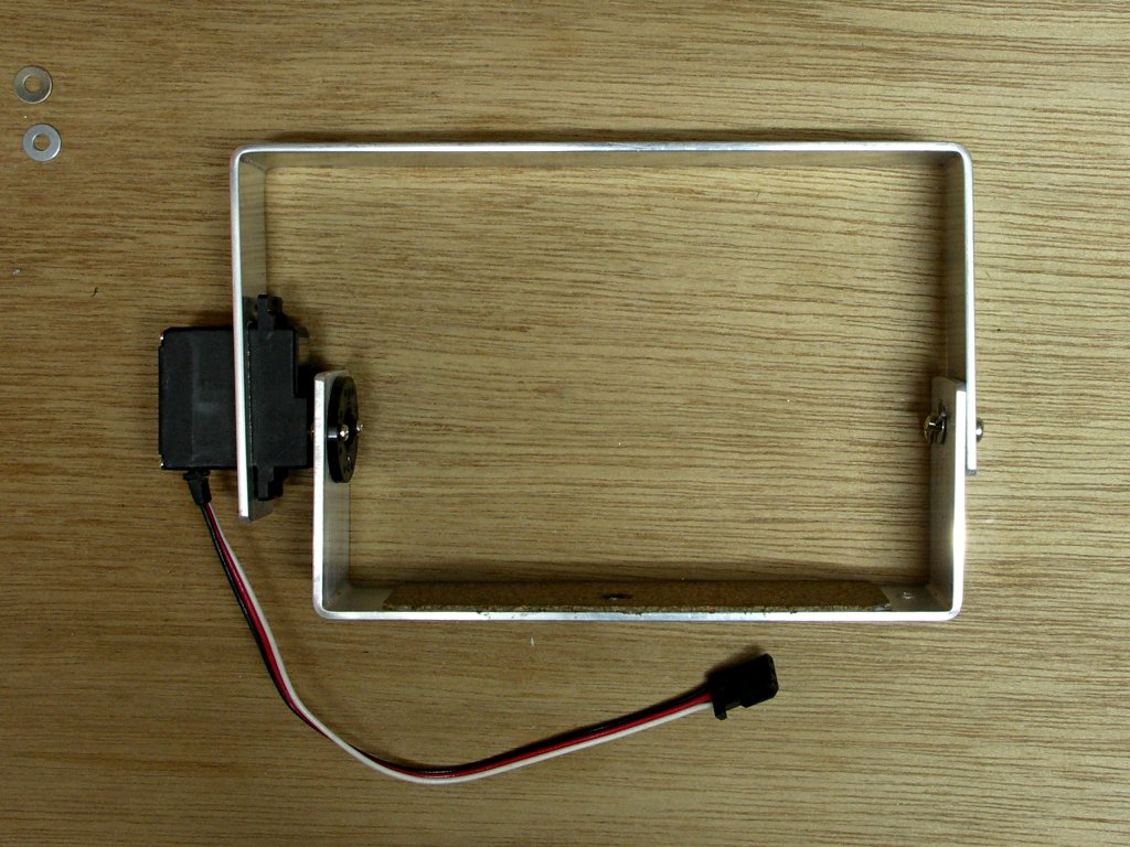
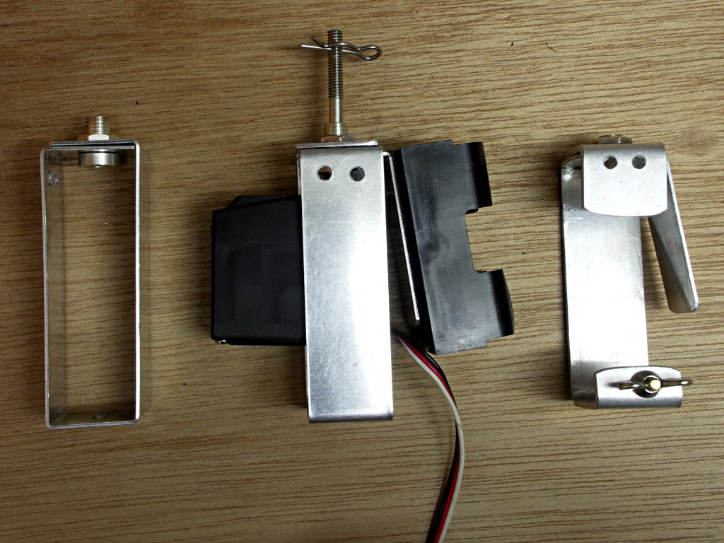 Collar chassis - 2 types
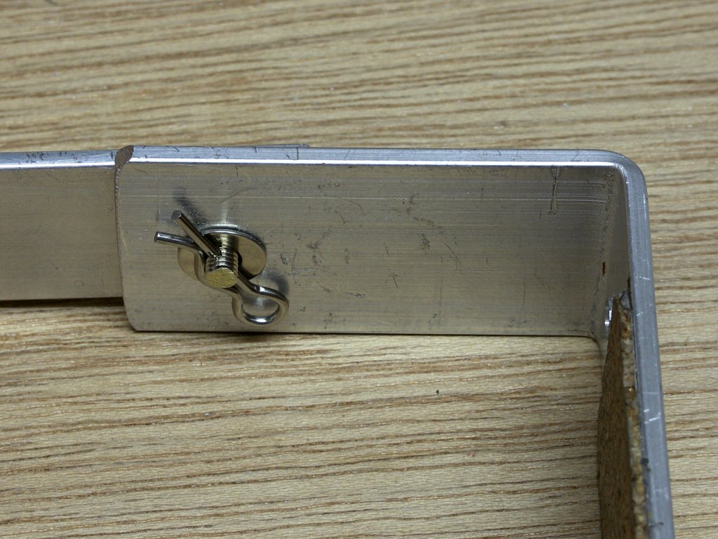
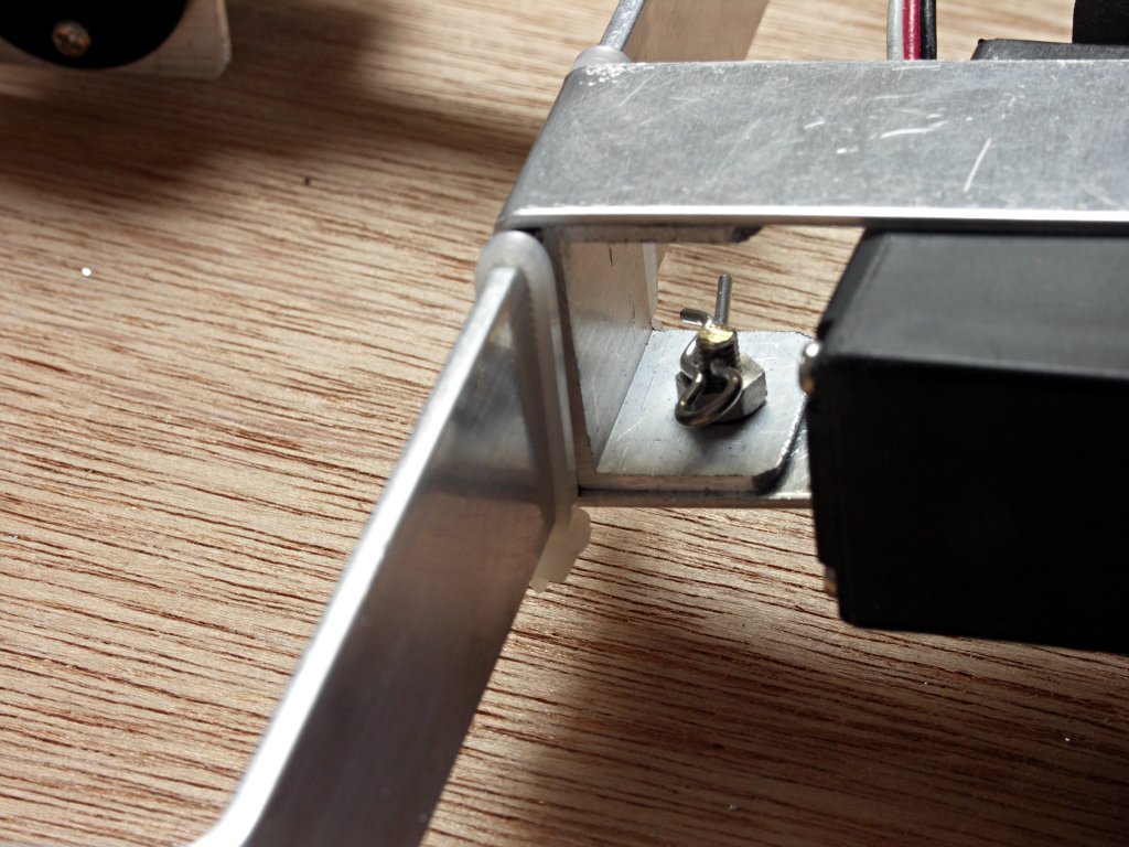
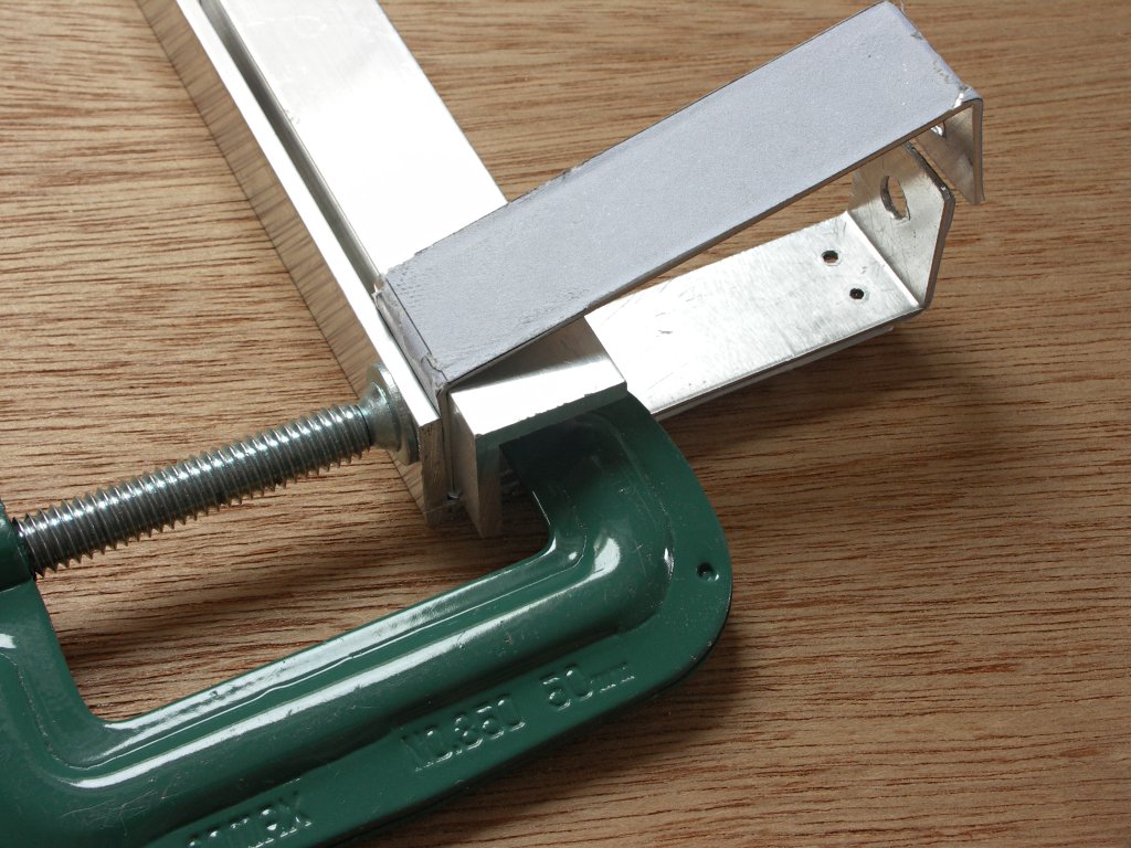 Last corner
|
That's it on the left of the picture. Just a frame linking the rig together with a servo inside it. This simplicity is possible because Tucit is able to give you very controlled panning without external gears.
Easy version Using 1 mm thick aluminium (picture left & centre which is the back view)
1 Print out the pdf plans. Check they are the right size, cut out the template and stick it with double sided tape to a strip of 1 mm x 20 mm aluminium.
2 Cut and file the ends and drill all the holes before folding.
3 You can bend the aluminium with the paper either on the inside or the outside.
4 With such thin aluminium a vice is preferable to a bending machine. Apply pressure as close to the vice as possible. Before removing tap it with a hammer through a piece of wood to sharpen the corners.
5 Work so that your bends don't reduce the width so always grip the thin bits and get the longer sides to do the bending.
|
6 Start with the outer bends. The final corner needs something different. As shown clamp the bottom section to a rectangular section or L section of aluminium which has a 20 mm side and bend around that.
7 Cut down and smooth a terminal as shown to make the collar then fit it.
8 Now check. Will a strip of 20 mm fit in the bottom ? Probably not so go back to step one and do a better one.
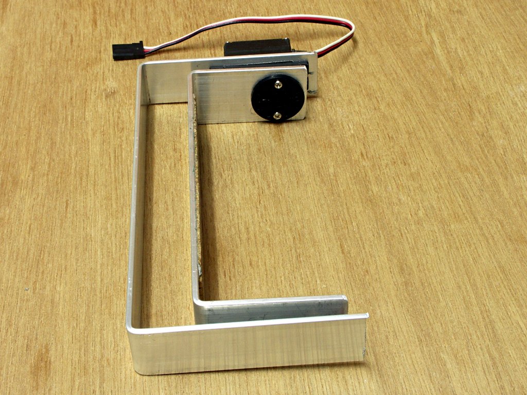
2 mm 'C' version (picture right which is the back view) Needs a bending machine
1 Adapt the plans to make a C section as shown. The side at the top with the 2 holes must extend low enough to restrain the side of servo and hold it in place.
2 The C version does not hold the upper U in the same 'wrap-around' way as the easy version and is harder to make. It's advantages are that it is shorter and if you have more than one UU frame for different cameras it is easier to change them.
The battery holder Using 1 mm aluminium
1 Now cut out and fit a 1 mm x 20 holder for a 9 volt battery holder.
2 Why put the battery there ? Because you want your rig to hang straight. You may be hanging this rig from a pendulum or a picavet. Imagine it's a pendulum. The weight of the servo is off the centre line so the pendulum won't be vertical. This leaves the best place to put either your controler or battery where it will counterbalance the servo.
3 Finally thread the servo through and when all is in place tighten the collar bolt.
|
|
|
5
|
THE PICAVET
|
|
|
 The picavet
 Picavet fastening
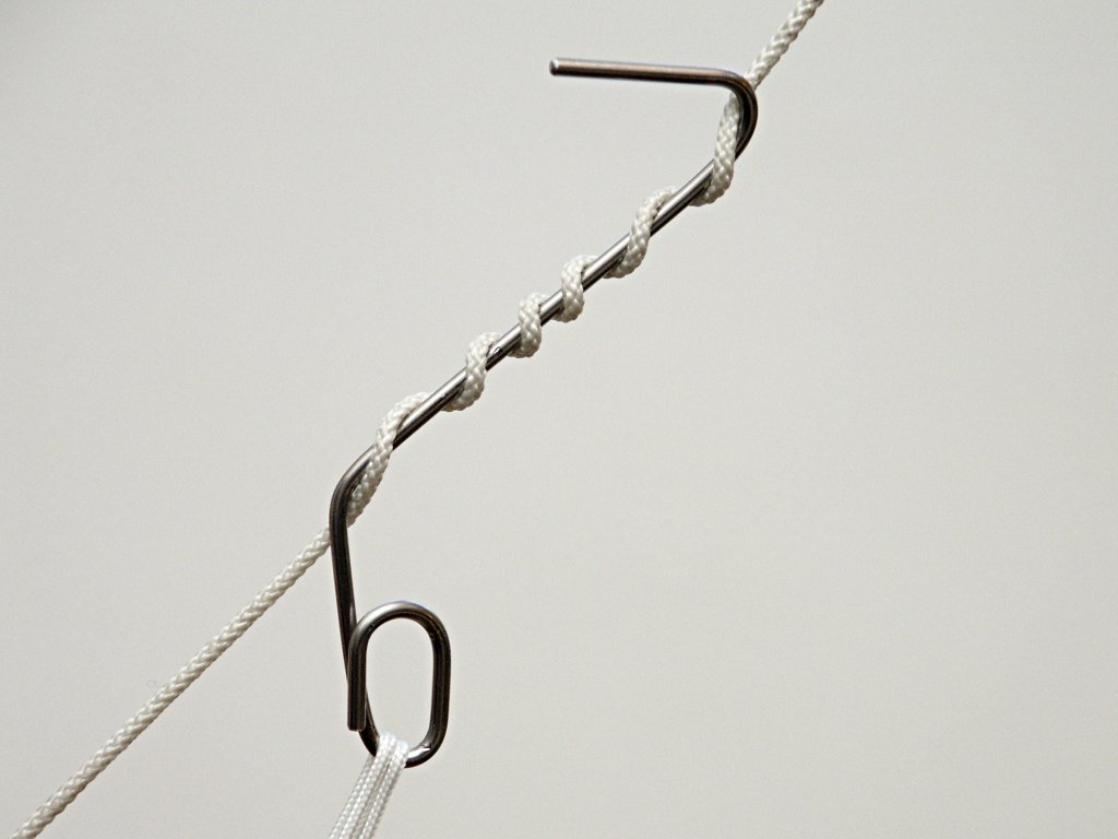 A hangup
|
There is plenty of information on the internet about the picavet and the best place to start is as always the Kaper. The cut out template I provide is for a picavet connecting to the pan bolt using the second electrical terminal and an R pin.
1 Stick the picavet template onto a piece of 2 mm aluminium sheet with double sided tape. Drill the holes as marked, cut out and file to the outline.
2 Assuming you have 3 mm eye bolts use a 3 mm tap into the 2.5 mm holes you have drilled. Fit the eyebolts (they all lie in the same direction), tighten the nuts, cut of the unecessary bolt ends and use locktite or similar on the bolts.
3 Cut down your second electrical terminal to the shape shown and bolt it on.
4 To make the 2 hangups use 15 cm lengths of 2 mm piano wire and a wire bender or follow the instructions in the Kapper with softer wire.
5 2 mm piano wire is quite hard to cut with a hacksaw and and you need a cheap wire bender. But it's good for this reason; as you force the end around to make the loop at the end there is bound to be an embarrassing gap where they cross. But that's actually a good thing. Pull them back and force them to cross the other way. This way they'll hold very tightly together with no chance of your string ever slipping through.
6 When you come to use your hangup give the line at least 6 turns around it.
7 Use 100 or 150 lb braided dacron and a washer or smooth polo shaped bead to complete your picavet.
|
|
Warning The tiny R pin may challenge your fingers at times. Good, please do not attach any kind of loop to it to make your life easier. This is your rigs weak spot. It is just not possible to predict what childs finger, birds claw, twig of tree you're dragging your kite out of might one day catch this loop. The smallest tug and your camera drops immediately. So plan for the inconceivable. Attach nothing to this pin, carry a quantity of spares and tape some to the rig.
|
|
|
6
|
THE LOWER U FRAME
|
|
|
|
|
 The camera bolt
 The lower U
 Balancing
 The tilt servo horn
|
1 You'll need a 1/4 inch bolt for your camera. As I'm unable to find plastic ones I drill as many holes as I can into a metal one and finish off with a key ring.
2 The upper U must be made of 2 mm x 20 mm aluminium to fit through the collar chassis but you can choose any width for the lower U. Here I use 2 mm x 25 mm.
3 At this stage you must decide if want the option to transmit a video camera image down to the ground. If so plug a cable into the your camera's video output now.
4 Allowing at least 1 cm each side of the camera decide on the width of the lower U and a little more length to the uprights than you expect.
5 Cut and bend.
6 Mark and drill the the hole for the camera bolt. Add some thin cork using double sided tape if necessary.
Balancing the tilt axis
1 With double sided tape put small pieces of cardboard or polystyrene board on the outer sides.
2 Bolt the camera on and attach everything that is going to be attached when it flies.
3 Switch the camera on and set to wide zoom and infinity focus so that the lense is extended in the way it will be when you are using it.
4 Using two sharp objects and with a friend acting as catcher find the points at which your camera is perfectly balanced. At this position you can spin the camera but it should also have a slight preference for pointing down at your preferred kapping angle. This operation is most comfortably done on a bed that's why there's no picture.
5 Having put marks where you want them remove the camera and drill through with a 3 mm bit.
Finally
Fit the horn of your tilt servo on the side you want. Enlarge the hole, set it in as shown and use 2 mm bolts or some other means to secure it.
|
|
|
6
|
TILT SERVO AND UPPER U FRAME
|
|
|
 The UU frame
 Position to mark hole
 Tilt bolt with R pin on inside
|
I have used a Futaba s3101 servo. But there are many alternatives. However you must 2 mm x 20 aluminium for the upper U as it is to fit inside the collar chassis.
1 Cut the servo cutout first. Stick the paper template on, drill and file as shown.
2 Choose bolts or self tapping screws to attach the servo and drill 2 holes accordingly but don't fasten yet.
3 Work out how deep you want the upper frame and bend so that you have the first right angle. You can now fit the servo. The grommet will be a problem as the cutout doesn't allow for it. Use a small file and provide it the minimum assistance required.
4 Now scratch your head. Exactly where does the second bend go. Well if you know the gap on the servo side (which you can now measure) the top section must be (a) the width of the bottom section (b) plus the servo gap between the 2 pieces of metal (c) plus 2 mm aluminium thickness because on the other side the upper U will be outside the lower U (d) plus any gap on the opposite side. Well you don't really need more than 1 washer but here you should add a contingency of at least 3 mm. Bending aluminium never gives you perfect results. If the upper section is too wide you can fill it with expert looking washers. But if it's too short the joint will be permanently jammed.
5 Make the final bend. Now fit the horn to the servo as shown so that the 2 long sections are next to each other. When they are exactly parrallel you use the hole in the lower section to mark on the upper section where the drill the 3 mm hole.
Now assemble the UU frame Cut drill and pin a 3 mm bolt fit as shown adding washers to taste. Don't forget to screw the horn to the tilt servo.
|
|
|
7
|
GETTING IT ALL TOGETHER
|
|
|
 Balancing the UU frame
 The slider
|
1 Assemble the parts you have made so far together with the camera, battery and Tucit etc and hang it somewhere.
2 The UU frame is held safely inside the collar chassis but it is not fastened into position. Decision time.
Fixed balance
1 Slide the UU frame until your camera is horizontal. There is a 3 mm hole at the bottom of the collar chassis. Put a mark on the underside of the upper U. Now drill a hole and fit a bolt and nut and make secure with an R pin.
Adjustable balance
1 You need to use a U section of 2 mm aluminium which is 20 mm wide and about 10 mm high to make the slider block. Using the hole at the back of the collar chassis drill a hole through the block and bolt and pin as shown.
2 The slider will hold your upper U in position but it will not stop it from being pushed along it. So you can easily balance your rig for add-ons like video or do fine tuning.
3 Add a cable grip to each side as shown to hold it so that it won't move about in flight.
|
Whichever of these options you take there is just that one bolt that has to be removed if you want to fold your rig to make it compact for travelling.
Finally
Finally attach your electrics, plug in your servos and use cable ties and tape and velcro to make your rig as tidy as possible. Now find that kite and get those pictures.
|
|
|
|
|
|
| |
| | |